 Deutsch
An Arduino Nano is very cheap to get directly from China. But often these boards still have an old bootloader on board. This article explains how to reflash the bootloader of the Nano with the help of another Arduino.
Notice:
This is a translation of the German article. Please note that especially menu names, button labels, names, screenshots etc. might not be translated (correctly). Feel free to let us know in the comments if you notice any errors.
Is the old or new bootloader installed?
To find out, connect your Arduino Nano to your computer via USB cable and open the Arduino IDE. Choose the following example sketch under File -> Examples -> 01.Basics -> Blink. Under Tools -> Board select “Arduino Nano” and under Tools -> Port select the corresponding port of your Arduino Nano. Under Tools -> Processor select “ATmega328P” (and not “ATmega328P (Old Bootloader)”) and start the upload of the sketch.
Upload successful?
If the sketch upload was successful, then the new bootloader is already installed on your Arduino Nano and you can stop reading at this point 🙂
Upload failed?
If you get an error message similar to the following, then your Arduino Nano has the old (or no) bootloader installed.
         Using Port                    : COM16
         Using Programmer              : arduino
         Overriding Baud Rate          : 115200
avrdude: stk500_getsync() attempt 1 of 10: not in sync: resp=0x00
avrdude: stk500_getsync() attempt 2 of 10: not in sync: resp=0x00
avrdude: stk500_getsync() attempt 3 of 10: not in sync: resp=0x00
avrdude: stk500_getsync() attempt 4 of 10: not in sync: resp=0x00
avrdude: stk500_getsync() attempt 5 of 10: not in sync: resp=0x00
avrdude: stk500_getsync() attempt 6 of 10: not in sync: resp=0x00
avrdude: stk500_getsync() attempt 7 of 10: not in sync: resp=0x00
avrdude: stk500_getsync() attempt 8 of 10: not in sync: resp=0x00
avrdude: stk500_getsync() attempt 9 of 10: not in sync: resp=0x00
avrdude: stk500_getsync() attempt 10 of 10: not in sync: resp=0x00

avrdude done.  Thank you.

Beim Hochladen des Sketches ist ein Fehler aufgetreten
The error message can also contain other codes after “resp”, e. g.:
avrdude: stk500_recv(): programmer is not responding
avrdude: stk500_getsync() attempt 1 of 10: not in sync: resp=0x85
Now select “ATmega328P (Old Bootloader)” under Tools -> Processor and start the upload of the sketch again. This time the upload should be successful and the LED on the Arduino Nano should blink. In the output window of the Arduino IDE you will see “Upload complete” and more details about the upload process, for example:
         Using Port                    : COM16
         Using Programmer              : arduino
         Overriding Baud Rate          : 57600
         AVR Part                      : ATmega328P
         Chip Erase delay              : 9000 us
         PAGEL                         : PD7
         BS2                           : PC2
         RESET disposition             : dedicated
         RETRY pulse                   : SCK
         serial program mode           : yes
         parallel program mode         : yes
         Timeout                       : 200
         StabDelay                     : 100
         CmdexeDelay                   : 25
         SyncLoops                     : 32
         ByteDelay                     : 0
         PollIndex                     : 3
         PollValue                     : 0x53
         Memory Detail                 :

[...]

         Programmer Type : Arduino
         Description     : Arduino
         Hardware Version: 2
         Firmware Version: 1.16
         Vtarget         : 0.0 V
         Varef           : 0.0 V
         Oscillator      : Off
         SCK period      : 0.1 us

avrdude: AVR device initialized and ready to accept instructions

Reading | ################################################## | 100% 0.00s

avrdude: Device signature = 0x1e950f (probably m328p)
avrdude: reading input file "C:UsersuserAppDataLocalTemparduino_build_372348/Blink.ino.hex"
avrdude: writing flash (924 bytes):

Writing | ################################################## | 100% 0.29s

avrdude: 924 bytes of flash written
avrdude: verifying flash memory against C:UsersuserAppDataLocalTemparduino_build_372348/Blink.ino.hex:
avrdude: load data flash data from input file C:UsersuserAppDataLocalTemparduino_build_372348/Blink.ino.hex:
avrdude: input file C:UsersuserAppDataLocalTemparduino_build_372348/Blink.ino.hex contains 924 bytes
avrdude: reading on-chip flash data:

Reading | ################################################## | 100% 0.22s

avrdude: verifying ...
avrdude: 924 bytes of flash verified

avrdude done. Thank you.Now we know that the old bootloader is installed on the Arduino Nano. We can overwrite this with the new bootloader without any problems, because it is only a different software. The hardware of an Arduino Nano with the old bootloader is no different from one with the new bootloader. But why should we do this at all?
Differences of the new bootloader compared to the old one
The old bootloader is the “ATmegaBOOT”, the new bootloader is called “optiboot” and is also used in other Arduino models.
In this StackExchange post, the two main benefits are mentioned:
- If the Arduino Nano is reset by the watchdog, then a bug in ATmegaBOOT causes the Arduino Nano to restart infinitely often. This bug does not exist in optiboot.
- When uploading sketches ATmegaBOOT works with a baud rate of 57600. The bootloader optiboot on the other hand is twice as fast with a baud rate of 115200. So sketches can be uploaded to the Nano faster with the new bootloader. Since different baud rates are used, the correct bootloader must always be selected when uploading sketches in the Arduino IDE. From the bootloader’s point of view no useful data would be received otherwise, because the sketch is transferred too slow or too fast.
Another small advantage of the new bootloader is that you can use the default setting of the Arduino IDE and don’t have to remember to change the bootloader in the “Processor” menu accordingly.
Flashing a new bootloader to the Arduino Nano
To flash a bootloader to an Arduino, you need a “programmer”. This can either be a special board for this purpose or you use another Arduino for this task. If you have a second Arduino lying around, it is recommended to use it as a programmer, because then you don’t have to buy an extra (rarely used) programmer board.
In the following we use an Arduino Uno as programmer. We also need six male-to-female jumper cables and the Arduino IDE must be installed; because flashing bootloaders via the web editor is not possible.
Prepare Arduino as programmer (ISP = In-System Programmer)
First we load the software on the Arduino Uno, with which we will flash the bootloader of the Arduino Nano later.
- Do not connect any jumper cables to the Arduino Uno yet.
- Connect the Arduino Uno via USB cable to the computer.
- Open the Arduino IDE (Note: Arduino create Web-Editor does not have the functions for bootloader flashing built in!) and load the sketch “ArduinoISP” via the menu
File -> Examples -> 11.ArduinoISP -> ArduinoISP - Set the board and port settings according to the used Arduino model for the programmer:
Tools -> Board -> Arduino UnoTools -> Port -> Select port number of the Arduino Uno
- Upload the sketch to the Arduino Uno.
- If everything is uploaded successfully, your ISP Arduino is ready to go!
Wiring: Connect Arduino Uno (programmer) to Arduino Nano (bootloader target device)
In the next step, we will connect the Arduino Uno to the Arduino Nano using six jumper cables.
- Disconnect the Arduino Uno (programmer) from the computer.
- There are two options for wiring the Arduino Nano (bootloader target device): the ICSP pin block or the normal, side pins.
Wiring using ICSP pin block
- The ICSP pin block consists of 2×3 pins labeled “ICSP” on the Arduino board. We will connect the Arduino Uno (programmer) to these six pins to flash the Arduino Nano’s bootloader. The ICSP pins are standardized and should have the same pinout on every Arduino model.
- A look into the code of the “ArduinoISP” sketch tells us how to wire the Arduino Uno (programmer) to the Arduino Nano (bootloader target device):
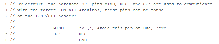
- With the symbol ” ° ” it is indicated, which is pin 1, which should also be labeled with a “1” on the board.
- On the fifth, unlabeled pin (in the sketch comment) is normally RST (Reset).
- We now need to connect these six pins on the Arduino Nano to corresponding pins on the Arduino Uno. The source code tells us the pin number for the reset.
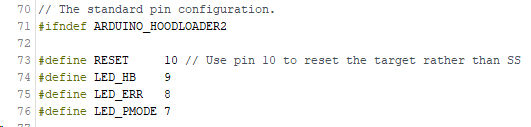
- Reset is triggered via pin 10.
- Reset: 10
- But which are the standard hardware pins for MOSI, MISO and SCK on the Arduino Uno? The pinout of the Arduino Uno tells us:
- MOSI: 11
- MISO: 12
- SCK: 13
- Furthermore we have to supply power to the Arduino Nano via the pins GND and 5V.
Alternative: Wiring via normal, side pins
In the comments it was pointed out that instead of the ICSP pinblock you can also use the normal, side pins of the Arduino Nano for the connection without any problems. In a corresponding pinout diagram you can quickly find out which are the required pins 5V, GND, SCK, MISO, MOSI and RST. In the following table both connection possibilities are listed. So the Arduino Uno is connected to the Arduino Nano in one of the following two ways:
| Arduino Uno (programmer) | <-> | Arduino Nano (bootloader target device) ICSP pin block | or: normal pins |
| 5V | – | 5V (ICSP-pin 2) | 5V |
| GND | – | GND (ICSP-pin 6) | GND |
| D13 | – | SCK (ICSP-pin 3) | D13 (SCK) |
| D12 | – | MISO (ICSP-pin 1) | D12 (MISO) |
| D11 | – | MOSI (ICSP-pin 4) | D11 (MOSI) |
| D10 | – | RST (ICSP-pin 5) | RST |
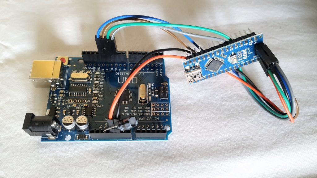
On the Arduino page about ISP it is pointed out that with the Arduino Uno as programmer (and also with the Mega, Mini and Nano) an additional 10µF capacitor must be connected to the pins GND (minus (-), short leg) and RST (plus (+), long leg). The capacitor may only be connected after the ArduinoISP sketch has been loaded onto the board. In the following photo you can see the additionally capacitor in place:

Note: In my case, the flashing process (see below) also worked without the additional capacitor. However, for two of our readers it did not work without a capacitor. In one case, a 0.1µF capacitor was sufficient. In the other case, a 10µF capacitor was used.
Start flash process
Now we can flash the new bootloader to the Arduino Nano.
- Change the settings in the Arduino IDE in the
Toolsmenu:- change
ProgrammertoArduino as ISP(choose exactly this entry and not “ArduinoISP” or “ArduinoISP.org”) - under
Portselect the port number of the Arduino Uno (programmer) - under
BoardandProcessorset the parameters for the “target Arduino” where we want to reflash the bootloader, so in this case:Board: Arduino NanoProcessor: ATmega328P(and not “ATmega328P (Old Bootloader)”)
- change
- In the menu
Toolsclick onBurn Bootloader. (Since no sketch is uploaded here, but the bootloader is transferred via the ArduinoISP program of the Arduino Uno, it doesn’t matter what sketch is open during this time).
The flash process only takes a few seconds (for me). When the bootloader has been flashed successfully, you will get a message that looks something like this:
         Using Port                    : COM16
         Using Programmer              : stk500v1
         Overriding Baud Rate          : 19200
         AVR Part                      : ATmega328P
         Chip Erase delay              : 9000 us
         PAGEL                         : PD7
         BS2                           : PC2
         RESET disposition             : dedicated
         RETRY pulse                   : SCK
         serial program mode           : yes
         parallel program mode         : yes
         Timeout                       : 200
         StabDelay                     : 100
         CmdexeDelay                   : 25
         SyncLoops                     : 32
         ByteDelay                     : 0
         PollIndex                     : 3
         PollValue                     : 0x53
         Memory Detail                 :

[...]

         Programmer Type : STK500
         Description     : Atmel STK500 Version 1.x firmware
         Hardware Version: 2
         Firmware Version: 1.18
         Topcard         : Unknown
         Vtarget         : 0.0 V
         Varef           : 0.0 V
         Oscillator      : Off
         SCK period      : 0.1 us

avrdude: AVR device initialized and ready to accept instructions

Reading | ################################################## | 100% 0.02s

avrdude: Device signature = 0x1e950f (probably m328p)
avrdude: NOTE: "flash" memory has been specified, an erase cycle will be performed
         To disable this feature, specify the -D option.
avrdude: erasing chip
avrdude: reading input file "C:UsersuserAppDataLocalArduino15packagesarduinohardwareavr1.8.2/bootloaders/optiboot/optiboot_atmega328.hex"
avrdude: writing flash (32768 bytes):

Writing | ################################################## | 100% 0.00s

avrdude: 32768 bytes of flash written
avrdude: verifying flash memory against C:UsersuserAppDataLocalArduino15packagesarduinohardwareavr1.8.2/bootloaders/optiboot/optiboot_atmega328.hex:
avrdude: load data flash data from input file C:UsersuserAppDataLocalArduino15packagesarduinohardwareavr1.8.2/bootloaders/optiboot/optiboot_atmega328.hex:
avrdude: input file C:UsersuserAppDataLocalArduino15packagesarduinohardwareavr1.8.2/bootloaders/optiboot/optiboot_atmega328.hex contains 32768 bytes
avrdude: reading on-chip flash data:

Reading | ################################################## | 100% 0.00s

avrdude: verifying ...
avrdude: 32768 bytes of flash verified
avrdude: reading input file "0x0F"
avrdude: writing lock (1 bytes):

Writing | ################################################## | 100% 0.02s

avrdude: 1 bytes of lock written
avrdude: verifying lock memory against 0x0F:
avrdude: load data lock data from input file 0x0F:
avrdude: input file 0x0F contains 1 bytes
avrdude: reading on-chip lock data:

Reading | ################################################## | 100% 0.01s

avrdude: verifying ...
avrdude: 1 bytes of lock verified

avrdude done. Thank you.Have fun with your freshly flashed Arduino Nano! 🙂
cover image: by Nizzah Khusnunnisa on Unsplash, modified with Canva
Leave a Reply